...

What Are the Best Machining Inserts for CNC Machining?

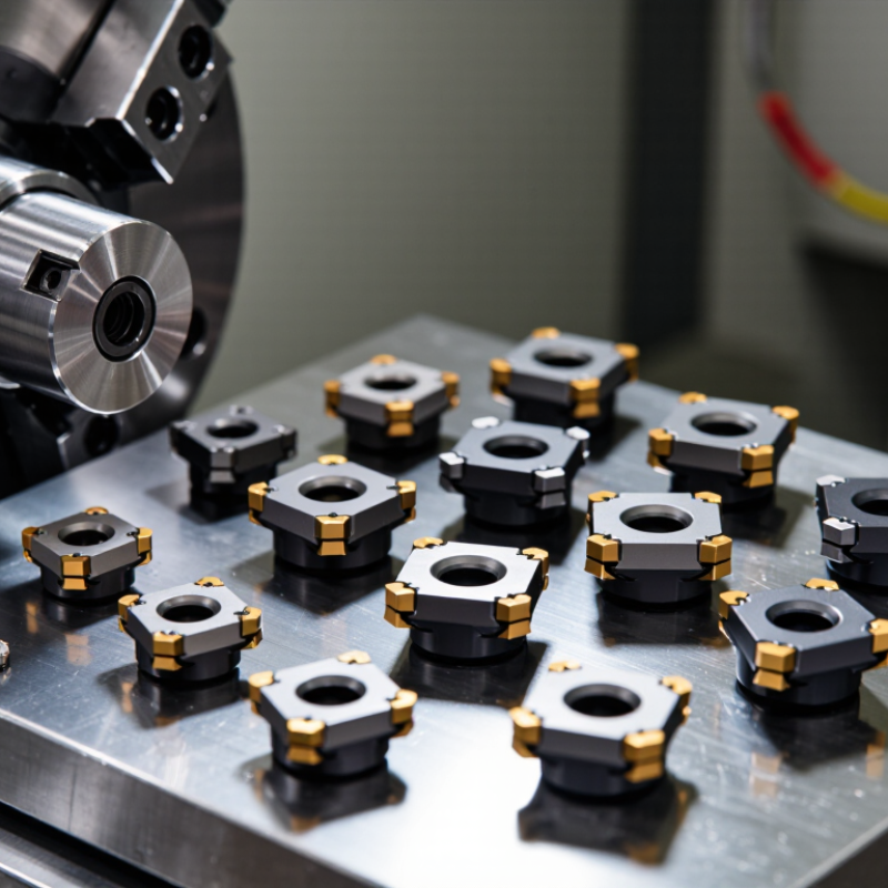
Choosing the best Machining Inserts is rarely a simple brand comparison. It depends on the workpiece, machine rigidity, cutting speed, coolant delivery, and production target. A sharp carbide insert may cut stainless steel cleanly, yet fail quickly on an interrupted cast-iron surface. The right choice is highly specific.

Industry data supports this careful approach. Grand View Research reports continued growth in the global machine tools market, driven by automation, aerospace production, and tighter manufacturing requirements. Deloitte’s 2024 Manufacturing Industry Outlook also identifies productivity, digital monitoring, and workforce efficiency as major priorities. These trends place more pressure on insert selection. A few seconds saved per cycle can become significant across thousands of components. However, published market forecasts are not machining recipes. They cannot replace a controlled cutting test.

Machining dynamics researcher Tony Schmitz has repeatedly emphasized that stable cutting conditions are essential for reliable performance. His practical message is clear: productivity must be increased without sacrificing process stability. That principle matters when comparing CVD-coated carbide, PVD-coated carbide, ceramic, cermet, and cubic boron nitride inserts. Geometry matters, too. A positive rake can reduce cutting force, while a stronger negative geometry may survive heavy interrupted cuts.

There is no universal winner. That answer sounds unsatisfying, but it is honest. Start with the insert manufacturer’s speed-and-feed guidance, then verify tool life, chip control, surface finish, and power consumption on the actual machine. Even experienced machinists sometimes optimize the wrong variable. A brilliant insert cannot rescue poor workholding, excessive runout, or an unstable setup.
What Are the Best Machining Inserts for CNC Machining?

Define “Best” by ISO 513 Tool Classes and Workpiece Material

The best machining insert is not universal. Define “best” through ISO 513 tool classes and the workpiece material first. P covers steel, while M suits stainless steel and K targets cast iron. N is intended for non-ferrous metals. S handles heat-resistant alloys and titanium, while H serves hardened materials.

Material behavior changes the cutting decision. A P-class insert may cut mild steel smoothly, but stainless steel needs stronger edge preparation and controlled heat. Cast iron often creates abrasive dust, so K-class geometry and a rigid setup matter. Aluminum belongs to N, where a sharp, polished edge helps prevent built-up material. For titanium, S-class inserts require stable clamping, moderate cutting speed, and reliable chip evacuation.

Tool life is only one measure. I also check cutting sound, chip shape, surface finish, and flank wear after several passes. A small insert can outperform a larger one when access is limited. Interrupted cuts may need a tougher edge, even if the finish becomes slightly less refined. Coolant can help, but it is not a cure for poor workholding or incorrect speed. This is not foolproof. My first selection is sometimes wrong after the first test cut. ISO 513 narrows the choice; machine rigidity, insert geometry, feed, depth of cut, and production goals complete it.
What Are the Best Machining Inserts for CNC Machining?

Best is defined by the ISO 513 workpiece class and the established application range of each insert material family.

Relative suitability index: 100 indicates a primary, well-established application; 50 indicates specialized or limited use; 0 indicates that the insert family is generally not a primary choice. ISO 513 groups are P: steel, M: stainless steel, K: cast iron, N: non-ferrous metals, S: heat-resistant superalloys and titanium, and H: hardened materials. Final selection should also consider hardness, cutting speed, interrupted cuts, and coolant conditions.

Match Carbide, Cermet, Ceramic, CBN, or PCD to ISO Material Groups

The best CNC insert depends on the ISO material group, not simply the machine’s power.
ISO P covers steel, while M covers stainless steel. K represents cast iron, N includes aluminum and other nonferrous metals. S covers titanium and heat-resistant alloys, and H includes hardened steel.

Coated carbide remains the practical starting point for P, M, and many K applications. It tolerates variable cutting conditions and interrupted cuts better than harder materials. Cermet suits stable, light finishing cuts in steel. It can produce a bright surface, but it dislikes vibration and heavy interruptions. For K materials, ceramic inserts can support high-speed machining when the setup is rigid and dry cutting is acceptable.

Harder materials need careful matching. CBN is effective for H-group steels and selected cast irons, especially during finishing. PCD performs well on N-group metals, graphite, wood composites, and abrasive nonmetallic materials. It is usually a poor choice for ferrous alloys because high temperatures can accelerate chemical wear. That detail is easy to overlook.

Insert geometry matters too.

A sharp edge reduces cutting force in aluminum and titanium. A stronger edge handles cast iron or interrupted steel cuts. Coolant choice, tool overhang, and workholding can change the result more than expected. The ISO chart provides direction, not certainty. In practice, an insert that succeeds on paper may fail after a small change in speed, chip load, or material hardness. Testing one controlled variable at a time is slower, but often more reliable.

Set Insert Geometry with 3–15° Rake Angles and Suitable Nose Radii

What Are the Best Machining Inserts for CNC Machining?

Insert geometry should match the cutting conditions, not merely the workpiece material. A rake angle between 3° and 15° often provides a practical starting range for turning and milling operations. Lower positive rake angles strengthen the cutting edge and suit interrupted cuts. Higher rake angles reduce cutting forces and help control heat during continuous cuts. However, excessive rake can weaken the edge and cause chipping. Cutting data still needs adjustment.

Nose radius affects surface finish, tool strength, and cutting pressure. A small radius, such as 0.2 or 0.4 mm, works well near shoulders and on slender parts. It also reduces radial force, which can limit deflection.

A larger radius, such as 0.8 mm or more, can improve finish at suitable feed rates. It needs a rigid setup, though. Otherwise, chatter may appear across the workpiece.

In shop trials, I compare the programmed feed with the nose radius before changing the insert. Feed that is too high leaves visible scallops, even with a polished edge. I also inspect the chip color and edge wear after several passes.

One setup may perform well on a rigid machine but fail on a thin-walled component. I have sometimes chosen a stronger edge when a sharper one seemed more efficient. That choice reduced breakage, but the surface finish needed another pass.

Geometry is a compromise. Test cuts reveal the compromise.

Compare TiAlN and Al₂O₃ Coatings at Approximately 2–15 μm Thickness

What Are the Best Machining Inserts for CNC Machining?

TiAlN and Al₂O₃ coatings perform differently across real CNC cutting conditions. TiAlN, often applied from about 2 to 8 μm, offers strong hardness and oxidation resistance. It suits high-speed milling, hardened steels, and many nickel-based alloys. Its dark surface can also reduce visible wear during inspection. However, excessive thickness may weaken edge sharpness and increase chipping on small tools.

Al₂O₃ coatings commonly range from approximately 5 to 15 μm. They provide excellent thermal and chemical stability during continuous cutting. This makes them useful for cast iron, hardened steels, and operations generating intense heat. The trade-off is brittleness. Interrupted cuts, unstable fixturing, or vibration can fracture the ceramic layer quickly. In practical trials, substrate grade and edge preparation sometimes matter more than coating thickness alone. That detail is easy to underestimate.

Tips: Match thickness to the cutting load. Use thinner TiAlN for sharp edges and light finishing. Consider thicker Al₂O₃ for stable, continuous roughing. Check flank wear after a short test run. A coating that looks suitable on paper may fail under coolant changes or interrupted engagement. Keep notes on cutting speed, feed, tool life, and chip color. Small records reveal patterns. No insert wins every cut.

What Are the Best Machining Inserts for CNC Machining? - Compare TiAlN and Al₂O₃ Coatings at Approximately 2–15 μm Thickness

Evaluation Dimension TiAlN-Coated Carbide Insert Al₂O₃-Coated Carbide Insert Practical CNC Machining Implication
Typical coating thickness Approximately 2–5 μm for common PVD TiAlN coatings Approximately 5–15 μm for common CVD Al₂O₃ layers Thicker coatings can improve thermal shielding but may require stronger edge preparation and sufficient clearance.
Primary coating technology Usually PVD; deposited at a comparatively lower process temperature Usually CVD; deposited at a higher process temperature PVD is often suitable for sharper edges, while CVD commonly supports thick, wear-resistant multilayer systems.
Hardness and wear resistance High hardness and strong resistance to abrasive and adhesive wear; performance depends on composition and deposition parameters Very strong resistance to crater wear, flank wear, and chemical wear at elevated cutting temperatures Al₂O₃ is often advantageous in stable, high-temperature cutting; TiAlN is versatile across interrupted and general-purpose operations.
High-temperature stability Good oxidation resistance and thermal stability for many dry or minimum-quantity-lubrication operations Excellent thermal barrier behavior and chemical stability at high cutting temperatures Al₂O₃ generally performs well in continuous high-speed cuts, while TiAlN offers a broader balance of toughness and heat resistance.
Edge sharpness Can be applied in relatively thin layers, allowing a sharp or moderately honed cutting edge The thicker CVD system generally requires a more robust honed or chamfered edge TiAlN is typically more suitable for small tools, milling, profiling, and operations requiring a sharp edge.
Resistance to thermal shock Generally better suited to interrupted cutting and cyclic heating when supported by an appropriate substrate and edge design More sensitive to thermal shock and edge chipping during severe temperature cycling TiAlN is normally the safer choice for interrupted milling, unstable setups, and variable engagement.
Recommended workpiece materials Alloy steels, tool steels, stainless steels, cast irons, and selected nickel-based alloys Cast irons, carbon and alloy steels, and selected hardened or difficult-to-cut materials in stable cuts The correct grade also depends on hardness, abrasiveness, work-hardening tendency, and cutting stability.
Typical cutting environment Dry cutting, minimum-quantity lubrication, and conventional coolant use, subject to the insert manufacturer’s guidance Commonly selected for dry, continuous cutting where a stable thermal condition can be maintained Avoid sudden coolant application or interruption with hot Al₂O₃-coated edges unless the grade is specifically designed for it.
Best-fit machining operations Milling, drilling, turning with interrupted engagement, profiling, and general-purpose CNC work Continuous turning, high-speed roughing, and stable finishing or semi-finishing of ferrous materials Operation stability is often more important than coating name alone when selecting an insert.
Main limitations May wear faster than a thick CVD system in highly abrasive, continuous high-temperature turning Greater risk of edge chipping in interrupted cuts; the thicker coating may be less suitable for very sharp micro-edges Select the coating together with substrate toughness, edge preparation, chipbreaker geometry, and cutting parameters.
Overall selection tendency Best all-round option for versatile CNC machining and interrupted cutting Best option for stable, continuous, high-temperature machining where maximum wear resistance is required Neither coating is universally superior; application conditions determine the most effective insert.

Note: Thicknesses and performance descriptions are typical engineering ranges rather than universal specifications. Actual results depend on coating composition, deposition method, carbide substrate, edge preparation, workpiece material, cutting speed, feed, depth of cut, coolant strategy, and machine rigidity.

Validate Cutting Speed, Feed Rate, and Depth of Cut for Stable CNC Results

What Are the Best Machining Inserts for CNC Machining?

The best insert depends on the material, machine rigidity, and cutting conditions. A sharp geometry can reduce cutting force on aluminum, while a stronger edge suits hardened steel. In practice, insert selection alone does not guarantee stable results. Cutting speed, feed rate, and depth of cut must work together.

Begin with the insert maker’s recommended range, then run a controlled test cut. For medium carbon steel, a starting speed of 120–180 m/min, feed of 0.08–0.18 mm per tooth, and depth of cut of 0.5–1.5 mm may be reasonable. These values are not universal.

Check spindle load, chip shape, surface finish, and tool wear after each pass. A steady load matters more than chasing maximum speed. Watch the sound. A sharp, rhythmic cut often indicates better control. Chatter usually points to excessive overhang, depth, or speed.

Tips: Record every adjustment. Change only one variable at a time. Keep the insert firmly seated and verify the workholding setup before cutting. For finishing, reduce the feed carefully and maintain enough material for a clean pass. For roughing, avoid burying the insert in a deep cut without checking machine power. I sometimes start too cautiously, then lose production time. That mistake is still cheaper than ignoring vibration marks or a growing cutting edge. Recheck the setup after tool changes, because small height differences can alter chip load and finish.

en_USEnglish

PCD Inserts

PCBN Inserts

Solid CBN Inserts

PCD Milling Cutter

PCD Drilling Tools

PCD Reamer

Diamond Special Tool

Diamond Dressers