SUNDI TOOLS
- Copyright © Wuxi Sundi Precision Tools Co.,LTD All rights reserved.
- Site Map
Choosing an RF Amplifier in 2026 starts with a practical question: what signal needs strengthening, and in what setup? A compact receiver project may prioritize low noise and modest gain, while a test bench may need wider frequency coverage and stable output. The right choice depends on the full signal chain, not one impressive number on a product page.
This guide compares ten options by key specifications, intended applications, and practical trade-offs. It considers frequency range, gain, noise figure, output power, impedance, connectors, and cooling. Small details matter. A mismatched connector or insufficient power supply can complicate an otherwise suitable installation. Published specifications are useful, but results can vary with cables, source quality, load, and measurement conditions. That limitation deserves attention.
An amplifier with high gain is not automatically the best fit. Excess gain can amplify unwanted noise or push connected equipment beyond its comfortable range. Check the manufacturer’s documentation, confirm compatibility with your equipment, and follow applicable operating requirements. No model wins everywhere. The selections are intended to help readers narrow the field, whether they are assembling a home lab, improving a communications setup, or comparing components for a technical project. Treat rankings as a starting point, then match each device to your actual frequency band, budget, and performance needs. A little uncertainty remains: specifications alone cannot predict every real-world result.
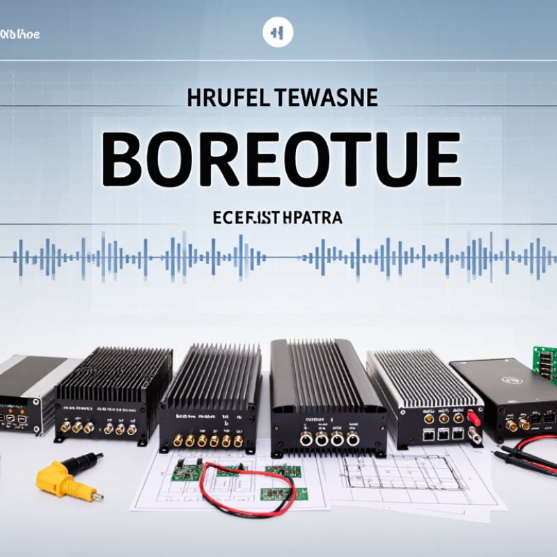
An RF amplifier raises the power of a radio-frequency signal so it can travel farther or be detected more reliably. It does not invent signal information: a transistor uses energy from a DC supply to reproduce the incoming waveform at a higher level.
A receiver’s low-noise amplifier boosts faint signals near the antenna, where cable losses could otherwise bury them. A transmitter’s power amplifier raises the signal before it reaches the antenna. Placement matters.
Gain is only part of the job. Engineers also check noise, impedance matching, linearity, and heat. Poor matching can reflect power back along a coaxial cable; excessive heat can shift performance.
These figures show the scale of connected communications that depends on reliable radio links, not a guarantee that every amplifier suits every circuit. That is the neat diagram; real boards are messier. A practical choice depends on frequency, input level, bandwidth, and the system’s noise and power limits.
RF amplifiers perform different jobs across a signal chain. A low-noise amplifier sits near a receiver antenna and raises weak signals while adding as little noise as possible. It is useful in satellite links, wireless receivers, and measurement systems. Power amplifiers work closer to the transmitter output. They deliver more signal power, but heat and distortion become important. Small heatsinks and careful airflow can make a real difference.
Driver amplifiers bridge the gap between signal sources and power stages. They help deliver a stable input to the final amplifier. Broadband amplifiers cover wide frequency ranges, while narrowband designs focus on a smaller range. A wider bandwidth is not always better; it can bring unwanted noise or make filtering harder. Check gain, noise figure, linearity, bandwidth, and input/output matching before choosing a type. Details matter.
Tips: Match the amplifier to the signal’s frequency and required output level. Check the datasheet’s compression and stability notes, not just its gain figure. If possible, test it with the cables and load you plan to use. Bench readings can differ from real setups. That is worth remembering.
A type-based buying guide rather than a brand ranking. Frequency and performance figures below are representative design ranges, not guaranteed specifications; confirm the datasheet for the exact operating band, impedance, cooling, and test conditions.
| No. | RF Amplifier Type | Typical Operating Range | Typical Performance Profile | Common Applications | Best Buying Fit | Key Check Before Purchase |
|---|---|---|---|---|---|---|
| 1 | Low-Noise Amplifier (LNA) | From HF through microwave bands; band-specific models are common | Often 10–25 dB gain; noise figure can be below 2 dB in suitable designs | Receiver front ends, satellite links, radar, radio astronomy, and weak-signal measurement | Weak-signal reception | Noise figure, input protection, gain flatness, stability, and whether the stated noise figure applies across your band |
| 2 | Broadband Gain Block | Commonly MHz to several GHz; some designs extend into microwave frequencies | Typically moderate gain, around 10–20 dB; output compression and linearity vary by device | Test equipment, signal-chain buffering, instrumentation, and general-purpose RF stages | General-purpose gain | Usable bandwidth, output 1 dB compression point, stability, and required bias or matching components |
| 3 | RF Driver Amplifier | Band-specific models span VHF, UHF, cellular, and microwave ranges | Provides intermediate gain and output power to drive a following stage; commonly specified by gain and output P1dB | Transmitter chains, laboratory signal sources, and the input stages of power amplifiers | Driving the next stage | Required drive level, gain flatness, linearity, operating bandwidth, and thermal limits |
| 4 | Class A Power Amplifier | Available from lower RF bands to microwave frequencies, depending on design | Conducts throughout the signal cycle; generally offers good linearity but lower efficiency than switched or highly tuned classes | Linear laboratory transmitters, instrumentation, and applications where signal fidelity is important | Linearity first | Output power, efficiency at the actual operating level, heat-sink requirements, and linearity metrics |
| 5 | Class AB Power Amplifier | Common across VHF, UHF, and microwave bands | A widely used compromise between linearity and efficiency; performance depends on bias, frequency, and output level | Communications transmitters, broadcast equipment, and general RF power stages | Balanced performance | Adjacent-channel or intermodulation requirements, bias conditions, efficiency, and cooling |
| 6 | Class C Power Amplifier | Usually designed for a specific RF band or narrow frequency range | High efficiency is possible with constant-envelope signals; substantial distortion makes it unsuitable for many linear modulation formats | FM transmitters, certain telemetry links, and other constant-envelope RF systems | Efficiency for constant envelope | Signal modulation, required filtering, tuned load, output power, and allowable harmonic emissions |
| 7 | Doherty Power Amplifier | Primarily used in cellular and other defined communications bands | Combines carrier and peaking amplifier paths to improve efficiency at backed-off output levels | Base stations and transmitters carrying high peak-to-average-ratio signals | Backed-off operation | Target band, instantaneous bandwidth, linearization needs, output back-off efficiency, and system-level load conditions |
| 8 | Envelope-Tracking Power Amplifier | Band- and system-specific; often selected for modern wideband transmitters | Uses a dynamically varying supply voltage to improve efficiency over changing signal power levels | Mobile and wireless transmitters with demanding efficiency and linearity requirements | Efficiency with varying signals | Envelope bandwidth, supply modulator compatibility, calibration complexity, and complete-system efficiency |
| 9 | Distributed Amplifier | Broadband designs may cover multiple octaves and can extend into microwave or millimeter-wave bands | Wide bandwidth is achieved using distributed transmission-line structures; gain and output power depend on frequency and implementation | Wideband test systems, electronic warfare, high-speed instrumentation, and broadband receiver or transmitter chains | Very wide bandwidth | Gain across the full band, noise figure or output power as relevant, group delay, and connector or package frequency limits |
| 10 | Integrated RF Front-End Module | Usually optimized for specified wireless bands rather than continuous broadband coverage | May combine a power amplifier with filtering, switching, or receive-path functions; ratings are system- and band-dependent | Compact wireless devices, IoT radios, and cellular or Wi-Fi equipment | Compact integration | Supported bands, control interface, transmit power, receive-path specifications, antenna matching, and regulatory requirements |
A useful RF amplifier comparison starts with frequency range, gain, and output power. The stated frequency band should cover your entire signal, not just its center. Gain, measured in decibels, indicates how much the amplifier raises signal level. More gain is not always better. Excess gain can overload the next receiver stage, especially when nearby signals are strong. Small numbers matter. Check whether the listed output power refers to compression or a linear operating point.
Linearity helps show how faithfully an amplifier handles stronger or multi-tone signals. Look for output third-order intercept and 1 dB compression figures, while noting the test conditions behind them. A low noise figure matters more in weak-signal receive paths than in many transmit applications. These figures can be easy to compare on paper, but they do not predict every setup. Cable loss, filtering, and input level all change the result.
Check impedance, usually 50 ohms, along with connector type and required supply voltage. Stability and thermal details deserve attention too. A unit may meet its ratings only with adequate airflow or a specified heat sink. Heat tells a story. In a compact enclosure, compare power draw and operating temperature rather than assuming the headline output is sustainable. Datasheets sometimes leave practical gaps, so confirm measurement conditions and allow margin for your actual signal levels.
Choosing an RF amplifier starts with the signal, not the largest gain figure. Match its frequency range to your application, then check gain and output power against the levels your system actually needs. Too much gain can drive later stages into compression. That creates distortion, even when the amplifier itself appears capable. Check noise figure for weak signals, and review linearity when signals are crowded or modulated. Small details matter.
Next, confirm the input and output impedance, supply voltage, and connector type. A mismatch can cause reflections and reduce delivered power. Look for stability information and thermal limits, especially if the unit will run inside a warm enclosure. A quick bench check helps. Measure gain across the intended frequency band, not just at one convenient point, and watch for unwanted oscillation. On paper, selection seems straightforward; in a real setup, cable loss, grounding, and heat can shift the results. Those effects are easy to underestimate. Leave some headroom rather than choosing a unit that barely meets the target. The ideal amplifier is not always the most powerful one; it is the one that behaves predictably in your full signal chain.
A useful 2026 RF amplifier shortlist should cover different jobs, not just chase the highest gain. Look for low-noise amplifiers for weak incoming signals, broadband units for flexible lab work, and power amplifiers for stronger transmissions. Also compare frequency range, gain flatness, noise figure, output compression, and heat management. A tiny module can run surprisingly hot.
Demand matters, too. GSMA Intelligence’s 2024 Mobile Economy report projected 5.5 billion 5G connections worldwide by 2030. Ericsson’s November 2024 Mobility Report forecast 6.3 billion 5G subscriptions by that year. These forecasts point to expanding radio networks, but they do not guarantee that any amplifier suits every setup. Check the actual operating band and required output before buying.
For a ten-item buying guide, compare options by use: cellular infrastructure, satellite links, test benches, and compact embedded systems. Favor published datasheets with measured performance across temperature, not a single impressive peak figure. Check connector type, supply voltage, and whether external filtering is needed. Measure twice. I would still leave room for doubt: headline gain figures can hide poor linearity or excess heat. A practical choice should match the signal chain, available cooling, and test results from your own bench.
Compare standard RF frequency bands to narrow down the amplifier range that fits your application.
The ranges shown are standard band classifications, not specifications for individual products. Before choosing an amplifier, check its supported frequency range, gain, output power, noise figure, and linearity.