...

What Is a Carbide Insert and What Is It Used For?

A Carbide Insert is a replaceable cutting tip used on turning, milling, drilling, and boring tools. It is commonly made from cemented carbide, where tungsten carbide particles are bonded with cobalt. This combination provides high hardness and strong resistance to heat and abrasion. In a machine shop, a sharp insert can remove material from steel, cast iron, stainless steel, aluminum, and selected nonmetallic materials. The result may be a clean shoulder, stable diameter, or controlled groove.

Small part. Serious work.

Unlike a brazed tool, an indexable insert can be rotated or replaced when one edge wears. Its geometry, grade, coating, and chipbreaker must match the workpiece and cutting conditions. A positive rake may reduce cutting forces in aluminum, while a tougher grade can tolerate interrupted cuts in cast iron. Coatings such as titanium aluminum nitride may improve performance, but they are not universal solutions. Excessive speed, poor clamping, or unsuitable coolant can still damage the edge within seconds.

This guide explains what a Carbide Insert is, how its shapes and codes are interpreted, and where common types are used. It also considers tool life, surface finish, safety, and practical selection. Manufacturer data remains essential because grades and recommended speeds differ. Shop experience matters too, but assumptions can be costly. An insert that works beautifully on one lathe may fail on another. That limitation deserves attention. Reliable results come from checking the material, machine rigidity, insert condition, and chip control before production begins.
What Is a Carbide Insert and What Is It Used For?

Carbide Inserts: Definition, Composition, and Basic Structure

What Is a Carbide Insert and What Is It Used For?

Carbide inserts are replaceable cutting tips used on lathes, milling machines, and drilling tools. Their main body is cemented carbide, not pure metal. Tungsten carbide particles provide hardness, while a metallic binder, commonly cobalt, holds the particles together. Typical grades contain about 70–97% tungsten carbide and 3–30% binder, depending on toughness and wear resistance.

The structure is more deliberate than it appears. A microscopic carbide grain forms the hard phase, and the binder fills the gaps between grains. Grain size strongly affects performance. Fine grains improve edge sharpness and wear resistance, while coarser grains usually tolerate impact better.

Many inserts also use a thin ceramic or carbide coating. It reduces friction, heat transfer, and chemical wear during cutting.

The United States Geological Survey reported approximately 84,000 metric tons of tungsten content mined worldwide in 2023. That figure shows the material’s industrial importance, but it does not explain every insert’s performance. Geometry, coating quality, workpiece material, coolant, and machine rigidity matter just as much. ISO 513 classifies cutting-tool materials by their resistance to wear and deformation, helping engineers match an insert to real cutting conditions. In practice, an insert that survives hardened steel may fail quickly in interrupted cast-iron cutting. The “best” grade is rarely universal. Trial cuts still matter.
How Carbide Inserts Are Manufactured and Classified

What Is a Carbide Insert and What Is It Used For?

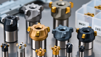
A carbide insert is a replaceable cutting tip used for turning, milling, and drilling operations. Its body usually contains tungsten carbide particles bonded with cobalt. This combination gives the insert high hardness, heat resistance, and useful toughness. Manufacturing begins with carefully measured powders. The mixture is pressed into a near-final shape, then sintered at high temperature. During sintering, the compact shrinks and becomes dense. Small dimensional errors can still appear.

After sintering, diamond grinding creates accurate edges, corner radii, and seating surfaces. Many inserts receive a coating through physical or chemical vapor deposition. Coatings can reduce friction, slow crater wear, and protect the substrate from cutting heat. However, a coating cannot correct poor cutting conditions. Excessive vibration may still chip the edge.

Carbide inserts are classified by shape, clearance angle, tolerance, chip-breaker design, and carbide grade. Common shapes include triangular, square, diamond, and round forms. The selected shape affects strength, accessibility, and the number of usable corners. Grades are matched to materials such as steel, stainless steel, cast iron, or heat-resistant alloys. A tougher grade may survive interrupted cuts, while a harder grade may resist wear during stable cutting. ISO-style identification codes help describe these features, but they are not always enough. Real results depend on machine rigidity, coolant delivery, workpiece hardness, and operator judgment. That last factor is easy to underestimate.

What Is a Carbide Insert and What Is It Used For?

Typical cobalt-binder content in cemented-carbide insert grades

Cemented-carbide inserts are cutting tools made mainly from tungsten carbide particles bonded with cobalt and consolidated by powder pressing and sintering. The representative binder values shown here illustrate a common relationship: lower cobalt content generally supports higher hardness and wear resistance, while higher cobalt content generally improves toughness and resistance to edge chipping. Actual compositions vary by insert grade, grain size, additives, and the ISO application group selected for the workpiece.

How Carbide Inserts Work in Cutting Operations

What Is a Carbide Insert and What Is It Used For?

How Carbide Inserts Work in Cutting Operations

A carbide insert is a replaceable cutting tip used on turning, milling, and drilling tools. It usually combines tungsten carbide particles with a metallic binder. This structure gives the insert high hardness and useful resistance to heat and abrasion. Small geometry changes matter. The nose radius, rake angle, and clearance angle control cutting pressure, chip flow, and surface finish.

During machining, the insert’s sharp edge shears a thin layer from the workpiece. The chip travels across the rake face, carrying much of the generated heat away. Clearance prevents the insert from rubbing against the fresh surface. If the edge becomes too blunt, cutting force rises, vibration appears, and the workpiece may show a rough, torn finish. A machinist can often hear this change before measuring it. That practical signal is useful, but not perfect.

Material demand explains the insert’s industrial importance. The U.S. Geological Survey’s Mineral Commodity Summaries 2025 estimated global tungsten mine production at about 81,000 metric tons in 2024. Tungsten carbide relies heavily on this hard material. The World Steel Association reported approximately 1.88 billion tonnes of crude steel production in 2023, indicating the scale of machining-related manufacturing. Still, harder is not always better. A very hard grade can chip under interrupted cuts, while a tougher grade may wear faster during continuous operations. Cutting speed, feed, coolant, workpiece hardness, and edge preparation must be matched carefully. Real workshops rarely follow one perfect formula.

Common Industrial Uses of Carbide Inserts

What Is a Carbide Insert and What Is It Used For?

Common Industrial Uses of Carbide Inserts

A carbide insert is a replaceable cutting tip made from hard tungsten carbide particles and a binding metal. It mounts into a holder on a lathe, milling cutter, or other machine tool. Unlike a solid cutting tool, the insert can be indexed or replaced after its edge wears. This reduces setup time and keeps production more consistent.

In turning operations, carbide inserts remove material from steel shafts, cast iron housings, stainless components, and nonferrous parts. Shops use them for facing, boring, grooving, threading, and profiling. Milling inserts shape flat surfaces, pockets, shoulders, and complex edges. Specialized inserts also support drilling and heavy roughing. Their performance depends on cutting speed, feed rate, depth of cut, and coolant control.

Small details matter.

Insert geometry affects chip flow and cutting pressure. A sharp edge may produce a cleaner finish, but it can fail during interrupted cuts. A stronger edge may survive vibration, yet leave more cutting resistance. In real production, selecting an insert is rarely perfect on the first trial. Operators often inspect chips, surface marks, sound, and tool wear before adjusting the setup. Incorrect clamping or excessive heat can damage an insert quickly. Reliable results come from following technical data, checking the workpiece material, and recording what actually happened on the machine.

Choosing the Right Carbide Insert for a Specific Task

What Is a Carbide Insert and What Is It Used For?

A carbide insert is a replaceable cutting tip used in turning, milling, and other machining operations. It usually contains hard carbide particles held in a metal binder. This structure resists heat, abrasion, and deformation better than many traditional cutting tools. Inserts come in different shapes, grades, edge preparations, and coatings. Each feature affects cutting performance.

Choosing the right carbide insert starts with the workpiece. Steel, stainless steel, cast iron, aluminum, and hardened materials require different cutting properties. A tough grade can handle interrupted cuts and vibration. A harder grade may provide longer life during steady finishing cuts. Choose the cutting geometry according to the operation. Roughing needs a strong edge and deeper chip space. Finishing often benefits from a sharper edge and smaller nose radius. Do not ignore machine rigidity. A flexible setup can damage even a suitable insert.

Cutting speed, feed rate, depth of cut, and coolant also matter. Check technical cutting data, then adjust it through controlled test cuts. My first choice is not always best. A large nose radius may improve surface quality, but it can increase cutting force. A small radius reduces force, yet it may wear quickly. Inspect the insert after each trial. Look for flank wear, built-up material, edge chipping, or unusual color. Secure seating and correct clamping are essential. Small setup errors can shorten tool life dramatically. Safety glasses and proper machine guarding remain necessary.

What Is a Carbide Insert and What Is It Used For? - Choosing the Right Carbide Insert for a Specific Task

Machining Task Recommended Insert Type Typical Workpiece Materials Recommended Geometry Common Coating or Substrate Key Selection Criteria Typical Applications
General rough turning Negative-rake insert Double-sided Carbon steel, alloy steel, cast iron Strong cutting edge with a medium or heavy chipbreaker Coated cemented carbide, commonly with wear-resistant layers such as titanium carbonitride, titanium nitride, or aluminum oxide Choose a strong insert shape, suitable nose radius, and a chipbreaker designed for high material-removal rates Removing large amounts of stock before finishing
General finish turning Positive-rake insert Single-sided Low-carbon steel, stainless steel, aluminum alloys, brass Sharp edge with a light chipbreaker and small to medium nose radius Fine-grain carbide; uncoated or coated carbide may be selected according to the workpiece Prioritize low cutting forces, good surface finish, and adequate edge stability Final sizing and surface finishing on shafts, sleeves, and faces
Stainless steel turning Positive-rake insert Sharp cutting edge Austenitic, ferritic, and martensitic stainless steels Polished rake face with a chipbreaker that controls long, continuous chips Tough, wear-resistant coated carbide or a grade formulated for work-hardening alloys Use a sharp edge, avoid dwell, and provide stable coolant delivery when appropriate Valves, fittings, medical components, and corrosion-resistant parts
Aluminum turning High-positive insert Polished edge Wrought and cast aluminum alloys, copper alloys Very sharp edge, large positive rake, and polished chip-contact surface Polished uncoated carbide or a coating with low aluminum adhesion Prevent built-up edge; use adequate cutting speed, chip evacuation, and a suitable nose radius Lightweight housings, automotive parts, and precision nonferrous components
Cast iron turning Negative-rake insert Reinforced edge Gray cast iron, ductile iron, compacted graphite iron Robust edge preparation with a chipbreaker suited to abrasive discontinuous chips Wear-resistant coated carbide; ceramic or cubic boron nitride may be considered for specialized high-speed work Control abrasive wear and protect the edge from interrupted cuts and hard spots Brake components, pump bodies, machine bases, and engine castings
Hard turning CBN insert Carbide for lighter work Hardened steels, typically above approximately 45 HRC Strong, accurately honed edge; geometry depends on hardness and interruption level Cubic boron nitride for high hardness; carbide is generally used below the effective hardness range of CBN Use high rigidity, minimal tool overhang, and a suitable edge preparation for interrupted or continuous cuts Replacing some grinding operations on gears, bearing seats, and hardened shafts
Grooving and parting-off Dedicated grooving insert Parting insert Steel, stainless steel, cast iron, aluminum, and nonferrous alloys Narrow, accurately ground cutting edge with chip-control features Coated or uncoated carbide selected for workpiece material and groove depth Match insert width to the required groove, maintain tool alignment, and ensure reliable chip evacuation Circlip grooves, oil channels, undercuts, and cutoff operations
Thread turning Profile-specific insert Partial or full profile Steel, stainless steel, cast iron, aluminum, and high-temperature alloys Insert profile must match the thread angle and pitch; full-profile inserts form the thread crest Fine-grain coated carbide for general work; specialized grades may be required for abrasive or heat-resistant alloys Select the correct thread standard, pitch range, hand, and insert profile before machining Internal and external metric, Unified, pipe, and other standardized threads
Shoulder milling Indexable milling insert 90-degree cutter geometry Steel, stainless steel, cast iron, aluminum, titanium alloys Positive geometry for lower cutting forces or stronger geometry for heavy-duty work Coated carbide chosen according to hardness, abrasiveness, and heat generation Consider cutter lead angle, radial engagement, axial depth, and machine-spindle rigidity Producing square shoulders, steps, and flat surfaces
Face milling Indexable face-milling insert Multi-edge design Steel, cast iron, aluminum, stainless steel Geometry selected for surface finish, cutting force, and interrupted-cut resistance Coated carbide for steels and cast irons; polished or specialized geometry for aluminum Choose an insert with the correct lead angle and wiper feature when a finer surface is required Large flat faces, plates, flanges, and machine components
Small-hole drilling Indexable drill insert Replaceable-tip drill insert Steel, cast iron, aluminum, stainless steel Center and peripheral inserts are often different to balance cutting speed across the hole diameter Coated carbide for steel and cast iron; polished carbide may suit aluminum Check drill diameter, hole depth, coolant access, point geometry, and insert position Through-holes, blind holes, and production drilling on CNC machines
Interrupted cutting Tough carbide grade Reinforced edge Forgings, keyways, castings, splined parts, and uneven surfaces Strong insert shape with a honed or chamfered edge and conservative chipbreaker Tough coated carbide or other impact-resistant cutting material Increase edge strength, reduce vibration, and use a rigid setup with controlled engagement Machining parts where the cutting edge repeatedly enters and exits the material

Selection note: Actual cutting speed, feed rate, and depth of cut depend on the insert grade, tool geometry, machine rigidity, workpiece hardness, coolant strategy, and cutting conditions. Always verify the recommended starting parameters in the insert manufacturer's technical data.

en_USEnglish

PCD Inserts

PCBN Inserts

Solid CBN Inserts

PCD Milling Cutter

PCD Drilling Tools

PCD Reamer

Diamond Special Tool

Diamond Dressers