SUNDI TOOLS
- Copyright © Wuxi Sundi Precision Tools Co.,LTD All rights reserved.
- Site Map
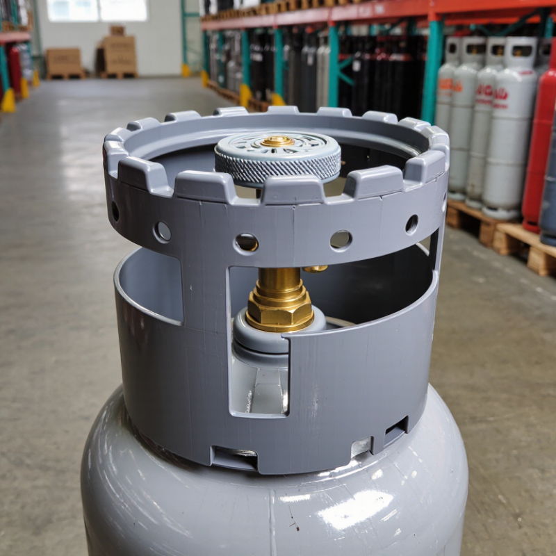
Choosing an Anti‑Collision Cylinder Cap is not a decorative decision. It affects safety, cylinder life, maintenance time, and handling confidence. In workshops, warehouses, laboratories, and transport areas, cylinders may contact walls, racks, floors, or other equipment. A suitable cap helps reduce impact around the valve and upper cylinder section. That protection matters when cylinders are moved repeatedly, stored tightly, or exposed to uneven surfaces. Small design details matter.
A reliable choice begins with the cylinder’s size, valve arrangement, thread requirements, and operating environment. Check dimensions carefully. A cap that feels secure but leaves the valve exposed is not adequate. Review the material, impact resistance, temperature range, drainage, grip, and cleaning requirements. Rubber, polymer, and reinforced designs can behave differently under pressure, cold conditions, oil contact, or sunlight. Manufacturer specifications should guide the decision, not appearance alone. Independent test data, quality records, and clear installation instructions add confidence. Yet no product is perfect. Real-world wear can differ from laboratory results.
This guide explains how to compare protection, fit, usability, and total cost before purchasing. It also considers inspection routines, replacement intervals, and compatibility with existing handling equipment. Look for a cap that stays stable without forcing the cylinder or blocking identification marks. Avoid assuming the heaviest option is automatically the safest. Practical testing is valuable. Fit one sample, inspect contact points, and observe movement during normal handling. A careful decision protects equipment and people while reducing avoidable maintenance. Good selection starts with evidence, then improves through honest review.
An anti-collision cylinder cap helps control impact when a moving actuator reaches an unexpected obstacle. Its role is practical. It can absorb part of the shock, protect the cylinder head, and reduce damage to nearby fixtures. It cannot replace guarding, sensing, or emergency stopping.
ISO 12100 requires machinery risks to be assessed as a complete system, not by one component.
The International Federation of Robotics reported 541,302 industrial robots installed worldwide in 2023.
The need is growing with automation. More automated motion means more frequent high-speed interactions between cylinders, grippers, tooling, and workpieces. When choosing a cap, technicians should check impact energy, operating speed, cylinder bore, stroke, mounting space, and reset behavior.
A cap that handles static load may fail during repeated dynamic impacts. That difference is easy to miss.
Measure the real machine cycle. Record speed, mass, collision direction, and daily impact frequency.
Then compare those values with verified manufacturer test data, preferably under similar temperatures and loads.
Inspect sealing surfaces and fasteners during preventive maintenance. Dust, oil, and misalignment can weaken performance.
I have seen specifications selected from catalog load tables alone; that approach is convenient, but incomplete.
The cap should also work with the machine’s sensor logic and safety controls. Otherwise, it may hide a fault instead of preventing one.
Identifying the Required Cylinder and Cap Specifications
Choosing an anti-collision cylinder cap starts with the cylinder, not the cap. Record the bore, stroke, rod diameter, mounting style, port thread, and operating pressure. A compact ISO 6432 cylinder needs different cap dimensions from an ISO 15552 cylinder. Check the technical drawing, not only the catalogue photo. A small mismatch can shift the rod off-center.
Automation is expanding quickly. The International Federation of Robotics reported 541,302 industrial robots installed worldwide in 2023. More moving equipment means more opportunities for accidental contact. Measure the moving mass and approach speed, then estimate the impact energy. A cap rated for 10 bar may still fail under a sharp external strike. Pressure rating is not impact rating. Confirm the material, wall thickness, replaceable insert, temperature range, and fastening method.
Fit matters most. It really does. The cap must clear sensors, protect the rod seal, and avoid reducing the designed stroke. For outdoor or washdown areas, inspect corrosion resistance and sealing details. ISO dimensions improve interchangeability, but they do not guarantee collision protection. Ask the supplier for test conditions, including impact mass, speed, and mounting position. In practice, I have seen specifications copied from an older cylinder. That shortcut looked efficient, but the cap interfered with the sensor bracket. Recheck the complete assembly before approval.
| Selection Dimension | Recommended Specification or Range | Why It Matters for Anti-Collision Performance | Verification Details |
|---|---|---|---|
| Cylinder Bore | Typically 25–100 mm for general pneumatic applications | The bore determines the available pushing force. A correctly sized bore prevents the cylinder from stalling or applying excessive impact energy. | Calculate force using piston area and operating pressure. Allow for friction, load variation, and a suitable safety margin. |
| Rod Diameter | Common general-purpose sizes: 10–40 mm | A larger rod improves resistance to bending and buckling when the cylinder is exposed to side loads or sudden contact. | Check unsupported rod length, compressive load, mounting alignment, and the manufacturer's buckling limits. |
| Operating Pressure | Usually 0.4–0.8 MPa for industrial compressed-air systems | Pressure directly affects cylinder force and impact severity. Excessive pressure can increase collision energy and wear. | Confirm the cylinder's rated pressure, minimum operating pressure, and the actual regulated pressure at the port. |
| Stroke Length | Select the shortest stroke that covers the required travel; common ranges are 25–500 mm | An unnecessarily long stroke can increase rod deflection, stopping distance, and the space required for protective components. | Measure the complete operating travel, including clearance, end-of-stroke tolerance, and any required buffer distance. |
| Cap Function | Protective cap, bumper cap, or energy-absorbing cap matched to the rod end | The cap spreads contact force and can reduce direct metal-to-metal impact between the rod assembly and an obstacle. | Check the cap's contact surface, compression behavior, allowable impact load, and resistance to permanent deformation. |
| Cap Material | Polyurethane or elastomer for cushioning; engineering plastic for light contact protection; metal only for structural shielding | Softer materials generally absorb more impact energy, while harder materials provide better abrasion and shape retention. | Match hardness, temperature range, chemical exposure, UV exposure, and expected contact frequency to the application. |
| Cap Internal Fit | Internal diameter should closely match the rod-end diameter without binding | Excessive clearance can cause movement, uneven loading, and cap separation; an overly tight fit can restrict rod motion. | Measure the rod-end diameter, shoulder geometry, retention groove, and required installation clearance. |
| Attachment Method | Threaded, press-fit, retaining-ring, or mechanically fastened design | The attachment must withstand repeated impact, vibration, and any axial load transferred through the cap. | Confirm thread size and pitch, retention method, tightening requirements, and service access for replacement. |
| Cushioning and End-of-Stroke Control | Adjustable air cushioning or external shock absorption where stopping speed is high | A cap alone is not a substitute for controlled deceleration at the end of a cylinder stroke. | Evaluate load mass, travel speed, cycle frequency, and available stopping distance before selecting the damping method. |
| Operating Speed | Use the cylinder's rated speed; reduce speed when contact or collision risk is present | Impact energy increases with speed. Lower approach speed reduces force transmitted to the cap, rod, and machine frame. | Check the minimum and maximum controllable speed using flow controls, pressure regulation, and the actual payload. |
| Mounting Alignment | Keep the cylinder axis aligned with the applied load; use guided support for side loads | Side loading can damage rod seals, increase friction, and cause premature cap or rod failure. | Inspect parallelism, guide clearances, mounting rigidity, and whether a separate linear guide is required. |
| Environmental Conditions | Common standard range: approximately 5–60 °C; verify for dust, moisture, chemicals, or outdoor use | Temperature and contamination can change elastomer hardness, sealing performance, and impact absorption. | Select compatible seal and cap materials, and confirm ingress protection, corrosion resistance, and cleaning requirements. |
| Safety and Replacement Check | Replace the cap when cracked, permanently compressed, loose, or chemically degraded | A damaged cap may no longer absorb impact or remain securely attached during repeated operation. | Lock out and depressurize the pneumatic system before inspection, removal, or replacement. |
Material choice affects both protection and daily handling. Thick rubber absorbs sharp impacts around the valve area. It also remains quieter on metal storage racks. Polyurethane usually offers better abrasion resistance, but it can feel less flexible in cold conditions. Steel provides excellent structural strength. However, it adds weight and may scratch nearby surfaces without a protective coating.
Design matters as much as material. A cap with reinforced ribs can spread impact forces across a wider area. Rounded edges reduce snagging during transport. Check the internal clearance carefully. A cap that presses against the valve may create unnecessary stress. Ventilation openings are also important when the design requires airflow. They should limit debris entry without blocking inspection access.
Look for secure attachment points. A loose cap can shift during handling. A locking ring, threaded connection, or fitted collar may prevent movement, depending on the cylinder design. Select a cap tested for the cylinder’s size, weight, and working environment. Workshop floors, outdoor yards, and vehicle loading areas create different risks. Do not rely on appearance alone. Inspect cracks, distorted ribs, and worn fastening points regularly. A heavy cap is not automatically safer. In practice, overbuilt designs can slow handling and encourage workers to remove them. That tradeoff deserves honest review.
How to Choose an Anti-Collision Cylinder Cap
Compatibility begins with the cylinder, not the cap. Check bore diameter, rod size, thread form, stroke length, and mounting space. A cap can fit mechanically yet interfere with sensors, hoses, or a moving load. ISO 4413 and ISO 4414 recommend verifying component suitability within the complete hydraulic or pneumatic system. Do not rely on catalog dimensions alone. Measure the installed assembly.
Safety depends on energy control. Review operating pressure, impact speed, cycle frequency, temperature, and expected side loading. A soft polymer cap may reduce contact noise, but it can deform under repeated impacts. A metal cap may resist crushing, but it can transfer force into the cylinder or frame. ISO 12100 places risk assessment before protective-device selection. That principle is easy to overlook.
The U.S. Bureau of Labor Statistics recorded 724 fatal occupational injuries involving contact with objects and equipment in 2023. This figure covers many industries, not cylinder caps specifically, but it shows why collision points deserve attention. Test the cap under realistic conditions, including misalignment and worn mounts. Inspect it for cracks, loosened fasteners, and permanent deformation. Replace it when protection becomes uncertain. Field experience often exposes weaknesses that a clean laboratory test misses. That is where judgment matters.
Choosing an anti-collision cylinder cap starts with accurate measurements. Record the cylinder diameter, rod clearance, mounting space, and maximum stroke. A cap that fits loosely may shift during impact. One that fits tightly can restrict movement or trap heat. Check the expected force, travel speed, and impact direction before selecting the material. Steel suits heavy impacts, while reinforced polymers can reduce weight and surface damage. Consider dust, moisture, oil, and temperature changes too.
I once focused too much on outer diameter and overlooked the rod extension. The cap looked correct, but it reduced usable travel by several millimeters. That small mistake mattered. Leave enough internal clearance for normal vibration, while avoiding gaps that invite debris. Review technical drawings and confirm the cap’s load rating with the cylinder specifications. Do not rely on appearance alone.
During installation, clean the mounting surface and inspect the cylinder for dents or misalignment. Position the cap squarely, then tighten fasteners evenly to the recommended torque. Use locking methods suitable for the equipment’s vibration level. After installation, move the cylinder slowly through its full stroke. Watch for rubbing, delayed motion, unusual noise, or loose hardware. Test it again under normal operating conditions. Recheck the fasteners after the first operating cycle. This step is easy to forget.