...

What Are the Top 10 Industrial EMC Solutions?

Industrial equipment rarely works alone. A motor drive, sensor cable, PLC, and switching supply share the same crowded cabinet. When electromagnetic interference disrupts that environment, symptoms can include false readings, resets, noisy signals, or unexpected downtime. The right Industrial EMC Solution helps equipment operate reliably without treating every disturbance as the same problem.

This guide introduces ten practical approaches, from enclosure shielding and bonding to power-line filtering, cable routing, ferrite suppression, and EMC testing. Each addresses a different coupling path. A filter may reduce conducted noise, while a properly terminated shield can limit radiated emissions. Small details matter: a long pigtail can weaken a cable shield, and a poorly bonded door can interrupt enclosure continuity. These are ordinary installation issues, not exotic failures.

Good selection begins with evidence. Engineers can inspect wiring, review equipment specifications, measure emissions or immunity, and compare results with applicable IEC 61000 test methods. Yet no single fix works everywhere. An added filter may affect leakage current or heat, while shielding can complicate maintenance. That trade-off deserves attention. The goal is not a perfect cabinet on paper, but stable performance beside real motors, relays, and long cable runs. Some sites still learn by trial and error; documenting each change makes the next decision better. This overview offers a grounded starting point for comparing solutions and asking better questions before buying components.
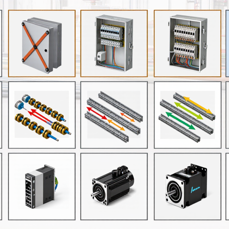
What Are the Top 10 Industrial EMC Solutions?

What Industrial EMC Means and Why It Matters

What Are the Top 10 Industrial EMC Solutions?
What Industrial EMC Means and Why It Matters

Industrial electromagnetic compatibility (EMC) describes equipment operating without creating or suffering disruptive electromagnetic interference. A variable-frequency drive can generate electrical noise; nearby sensors may then report unstable readings. Long cable runs, switching contactors, and poorly bonded enclosures can add risk. EMC has two sides: controlling emissions and maintaining immunity. Both matter. The IEC 61000-4 series specifies immunity test methods, including electrostatic discharge, radiated radio-frequency fields, and electrical surges. Passing a test does not guarantee flawless performance in every installation, but it gives engineers a repeatable benchmark.

The consequences deserve attention. Siemens’ 2024 True Cost of Downtime report surveyed 500 senior industrial decision-makers and found that unplanned downtime averaged 11% of annual revenue among surveyed companies. This figure is not specific to EMC failures. It does show why preventing avoidable interruptions matters. In a plant, one noisy signal can trigger a false alarm, stop a conveyor, or complicate fault-finding. The exact cause may be unclear at first; grounding, cable routing, and equipment settings can interact.

Tips: Keep power and signal cables separated where practical. Bond enclosure doors and panels with low-impedance connections. Check shield terminations and test equipment in its actual operating environment. Record interference symptoms before changing several things at once. That last step is easy to skip. It can save hours.


How Electromagnetic Interference Affects Industrial Systems

In a factory, electromagnetic interference rarely announces itself. A proximity sensor may flicker beside a motor, or a PLC may reset when a variable-speed drive starts. The line stops, yet the fault can look like bad software. EMI can enter through cables as conducted noise or couple through space as radiated noise. Fast switching, poor bonding, and long parallel cable runs can make both pathways worse. Small details matter.

EPRI’s 2001 report, The Cost of Power Disturbances to Industrial and Digital Economy Companies, estimated annual U.S. losses of $15–24 billion from poor power quality. That broad estimate includes disturbances such as sags and transients; it is not an EMI-only figure. Still, it shows why brief electrical events deserve attention.

A momentary sensor error can spoil a batch or trigger a safety stop. In practice, teams sometimes blame the controller first. That can waste a shift. Record the timing of faults, inspect cable routes, and compare events with drive starts. These clues help separate interference from failing hardware, though no single test tells the whole story.

Testing against the IEC 61000 series can help assess immunity under defined conditions. A shield alone is not a cure. Proper termination and grounding matter, too.

The Core Principles of Industrial EMC Control

Industrial EMC control begins with three questions: What is generating interference, how does it travel, and which device is affected? A variable-frequency drive may create high-frequency noise, while long sensor cables can carry it into a control input. Treat the source, coupling path, and susceptible equipment as one system. This is more useful than adding filters everywhere.

Reduce emissions at their source, then interrupt remaining paths with suitable shielding, filtering, and cable routing. Keep motor leads away from low-level signal cables, and cross them at right angles when separation is limited. Bond metal cabinet panels with clean, secure connections; paint beneath a bonding point can weaken electrical contact. Grounding details matter. A tidy drawing may not match the cabinet after installation, so inspect actual cable routes and terminations. Even one overlooked drain wire can complicate troubleshooting.

Tips: Check noisy equipment under load, not only while idle. Use an oscilloscope or EMC test equipment where appropriate, and change one variable at a time. Record the result. It is tempting to blame the newest device, but the real path may be older wiring.

How to read this chart: A filled cell indicates a control method commonly used to address that EMC path; a blank cell does not mean the method can never help. This is a qualitative engineering overview, not a measured performance ranking. Actual results depend on the design, installation, and test conditions.

Ten Common Solutions for Industrial EMC Problems

Industrial EMC faults often appear as sensor drift, nuisance resets, or noisy readings near a motor drive. Start with low-impedance bonding between panels, doors, and machine frames. Route power cables away from sensor and communication lines. Use shielded cables where interference is likely, and terminate their shields correctly at the equipment. Add ferrite cores to troublesome cables. Install line filters at the source of conducted noise. Small details matter.

Improve enclosure shielding by closing gaps around doors and access panels. Use conductive cable glands to maintain shield continuity at cabinet entries. Add surge protection to exposed power and signal lines. Review circuit-board layout to reduce loop areas and keep sensitive traces away from switching circuits. Inspect connectors for loose contacts, corrosion, or damaged shielding. No single fix works everywhere; a neat cabinet can still hide an intermittent noise source. Confirm changes with measurements under normal operating loads.

Tips: Change one variable at a time and record the result. Check the machine during startup, switching, and peak load, not only at idle. If a filter reduces one symptom but creates another, revisit the grounding path and cable routing before adding more components.

How to Select and Verify an EMC Solution

Selecting an industrial EMC solution starts with identifying how interference enters or leaves the equipment. Check whether the failure is conducted or radiated, and note the affected frequency range, operating mode, and cable layout. A filter may reduce noise on a power line, while shielding can limit radiated emissions. Ferrites, grounding changes, and improved enclosure bonding may help too, but none is a universal fix. Match the remedy to the measured path, not just the most visible symptom.

Verify changes under repeatable conditions. Keep cable lengths, loads, grounding, and equipment placement consistent between tests. Use a suitable receiver or spectrum analyzer, current probe, or near-field probe to locate emissions; formal compliance testing may require specialized equipment and procedures. Test the product in its realistic operating modes, including switching loads and communication activity. Record before-and-after results, test settings, and any trade-offs, such as added heat or reduced signal quality. Results can be messy. Recheck your assumptions when a fix shifts, rather than removes, a peak.

Tips: Change one variable at a time. Inspect seams, connector backshells, and cable entry points. Retest after every layout or enclosure change; small details can undo a promising result.

What Are the Top 10 Industrial EMC Solutions? — How to Select and Verify an EMC Solution

Industrial EMC Solution Typical Purpose How It Works Selection Considerations How to Verify
Protective bonding and grounding Reduce hazardous touch voltages and provide controlled paths for fault and high-frequency currents. Connects conductive enclosures, doors, panels, and equipment parts to a defined protective bonding system. Check applicable electrical-safety requirements, conductor size, connection impedance, corrosion protection, and continuity across moving or painted joints. Inspect connections and measure protective-conductor continuity using the test method and limits required by the applicable product standard.
Shielded enclosures and cabinets Limit radiated emissions from equipment and reduce susceptibility to external electromagnetic fields. Conductive walls reflect and absorb electromagnetic energy; seams, doors, and cable entry points must preserve shielding continuity. Consider operating frequency, required attenuation, enclosure material, seam design, ventilation, access panels, and the effect of apertures. Measure radiated emissions or immunity in an appropriate test setup. For enclosure-level characterization, use a defined shielding-effectiveness method and frequency range.
EMI filters on power and signal lines Attenuate conducted noise entering or leaving equipment through cables. Capacitors, inductors, and damping elements create frequency-dependent impedance that reduces unwanted common-mode or differential-mode noise. Match the filter to the noise mode and frequency; check current rating, voltage rating, insertion loss in the actual source/load impedance, leakage current, and safety approvals. Measure conducted emissions and immunity with the required line impedance stabilization network or coupling/decoupling network, as applicable.
Cable routing, separation, and termination Reduce coupling between noisy and sensitive circuits and control common-mode currents on cables. Physical separation, short return paths, suitable cable pairing, and correctly terminated shields reduce loop area and unwanted coupling. Separate power-switching and low-level signal wiring where practical; follow equipment-specific shield-termination requirements and avoid long, unbonded pigtails at high frequencies. Check wiring against drawings and installation requirements, then compare emissions and immunity results with representative cable lengths and routing.
Transient voltage suppression Protect interfaces and power inputs from electrostatic discharge, electrical fast transients, and surge events. Clamping or diversion components limit transient voltage and route transient current through a deliberate return path. Choose protection for the expected waveform, working voltage, clamping level, energy, repetition, line capacitance, and available discharge path. Test against the applicable immunity requirements, such as IEC 61000-4-2 for ESD, IEC 61000-4-4 for EFT, or IEC 61000-4-5 for surge.
Galvanic isolation Reduce conducted interference and ground-loop coupling between electrically connected subsystems. Transfers signals or power across an insulating barrier without a direct conductive connection. Verify working and transient isolation ratings, creepage and clearance, signal bandwidth, data rate, common-mode transient immunity, and safety requirements. Perform the insulation and dielectric tests required by the applicable safety standard; verify functional immunity under representative common-mode disturbance conditions.
PCB layout and return-path control Minimize emissions and susceptibility within electronic assemblies. Short current loops, continuous reference planes, controlled return paths, and careful placement reduce parasitic coupling and loop inductance. Review switching-node area, decoupling placement, connector transitions, plane splits, high-speed interfaces, and separation of noisy and sensitive circuits. Use design reviews and near-field probing for diagnosis, then confirm performance through the applicable conducted and radiated EMC tests.
Ferrite cores and common-mode chokes Suppress high-frequency common-mode noise on cables and selected circuit paths. Magnetic material or coupled windings add frequency-dependent impedance, reducing unwanted high-frequency current. Check impedance versus frequency, current capacity, core material, cable fit, temperature rise, and whether the dominant noise is common-mode or differential-mode. Measure cable or circuit noise before and after installation using suitable current probes or conducted-emissions measurements; confirm no adverse functional effects.
EMC cable glands, backshells, and conductive seals Maintain shielding continuity where cables enter enclosures and where panels or doors meet. Provides a low-impedance, circumferential conductive connection across cable entries, seams, and enclosure interfaces. Match the component to cable diameter, enclosure finish, environmental rating, corrosion conditions, compression range, and required shield termination. Inspect installation quality and bonding continuity; validate enclosure or system emissions and immunity with the final cable-entry configuration.
Isolation transformers and power-line conditioning Address selected power-quality and conducted-interference problems in industrial power systems. Transformer coupling provides galvanic isolation; suitable conditioning components can reduce certain disturbances when correctly specified and installed. Assess load, inrush current, frequency, grounding arrangement, fault protection, harmonic behavior, and the specific disturbance to be mitigated. Measure power quality and conducted disturbances at the relevant points, and verify equipment immunity and safe operation under the intended installation conditions.
en_USEnglish

PCD Inserts

PCBN Inserts

Solid CBN Inserts

PCD Milling Cutter

PCD Drilling Tools

PCD Reamer

Diamond Special Tool

Diamond Dressers