SUNDI TOOLS
- Copyright © Wuxi Sundi Precision Tools Co.,LTD All rights reserved.
- Site Map
 Skip to content
Choosing the right Solid Carbide Drill is not simply a matter of matching diameter and length. The best choice depends on the workpiece, hole depth, machine stability, coolant delivery, and required tolerance. In practical machining, a drill that performs well in hardened steel may fail quickly in aluminum or abrasive cast iron. Material changes everything.
Experienced machinists usually begin with the manufacturer’s cutting data, then adjust it carefully for real workshop conditions. Flute geometry, point angle, margin design, and coating influence chip evacuation, heat control, and tool life. A short, rigid drill often produces more reliable holes than a longer tool, especially on machines with vibration. Small details matter. Through-coolant can also improve performance in deep holes, but only when the machine supplies enough pressure and flow.
This guide explains how to compare drill specifications without relying on advertising claims alone. It considers hole diameter, depth-to-diameter ratio, workpiece hardness, spindle runout, and production volume. Independent recommendations should be checked against current technical data and the actual machine setup. No tool is universal. Even a premium Solid Carbide Drill can break when feed rates, alignment, or chip evacuation are poorly controlled. That limitation deserves attention. By combining verified manufacturer guidance with measured results from your own process, you can select a drill that balances accuracy, service life, surface finish, and total machining cost. The right decision is often less dramatic than expected, but it is usually more dependable.
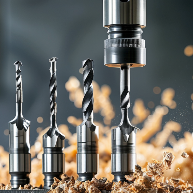
Choosing the right solid carbide drill starts with design, not diameter alone. Its carbide grade, flute geometry, point angle, and margin control cutting stability. A fine-grain substrate improves edge strength and wear resistance. However, excessive hardness can reduce toughness during interrupted cutting.
The USGS Mineral Commodity Summaries 2024 reported approximately 81,000 metric tons of global tungsten mine production in 2023. This supply supports carbide tooling, but material quality still varies by grade and binder content. ISO 513 groups hard cutting materials by application behavior, including wear resistance and toughness. A drill for hardened steel needs different geometry from one used in aluminum. Helix angle affects chip evacuation. A split point reduces thrust and helps prevent wandering. Coolant channels can protect the cutting edge during deep-hole work. Yet, published specifications never replace a real trial.
Tips: Match the drill to the workpiece first. Check hardness, hole depth, tolerance, and machine rigidity. For stainless steel, choose a geometry that reduces work hardening and evacuates chips quickly. For aluminum, polished flutes and a sharper point usually prevent built-up edge. Keep tool runout below 0.01 mm when tight tolerances matter. Measure it; do not assume it. I have seen a technically correct drill fail because the holder was dirty. That detail is easy to miss. Recheck feed and speed after observing chip color, sound, and hole-wall finish. Perfect selection remains partly judgment.
A practical comparison of the main design features and selection criteria for solid carbide drills
| Design Feature | Typical Options or Values | Primary Function | Recommended Selection Guidance |
|---|---|---|---|
| Drill Diameter | Commonly 0.5–20 mm; larger diameters are also available for specialized applications | Determines hole size, cutting load, rigidity, and achievable depth | Match the nominal diameter to the required hole tolerance and allow for any finishing operation such as reaming. |
| Length-to-Diameter Ratio | Short: approximately 3×D; standard: approximately 5×D; deep-hole: approximately 8×D or more | Influences tool rigidity, deflection, chip evacuation, and vibration risk | Use the shortest flute and overall length that can reach the required depth. Longer drills require more stable setup and better chip control. |
| Point Angle | Approximately 118°, 135°, or application-specific split-point geometries | Controls centering behavior, thrust force, and cutting-edge engagement | A 118° point is versatile for many general applications. A 135° split point can reduce walking and thrust when drilling harder materials or pre-existing flat surfaces. |
| Helix Angle | Low helix: about 10–20°; standard helix: about 25–35°; high helix: about 35–45° | Affects chip lifting, cutting smoothness, edge strength, and heat removal | Choose higher helix designs for ductile materials and chip lifting. Choose lower helix designs when edge strength and reduced grabbing are more important. |
| Core Thickness | Standard core or reinforced core geometry | Balances torsional strength against flute space for chip evacuation | Select a reinforced core for interrupted cuts, hard materials, or deep drilling. Use more flute space when chip volume is high. |
| Flute Design | Two-flute, four-flute, variable-helix, or specialized chipbreaker geometry | Provides chip channels and influences stability, surface finish, and evacuation | Use open flute space for long or continuous chips. Use variable geometry to help reduce harmonic vibration in demanding machining conditions. |
| Carbide Grade | Fine-grain or ultrafine-grain cemented carbide; typical cobalt content is approximately 6–12% | Determines hardness, toughness, wear resistance, and resistance to edge chipping | Choose a harder, wear-resistant grade for abrasive materials and stable cutting. Choose a tougher grade for interrupted cuts, vibration, or less rigid machines. |
| Coating | Uncoated; TiN; TiAlN or AlTiN; multilayer PVD coatings | Improves wear resistance, lowers friction, and can increase thermal stability | Use uncoated tools for selected nonferrous or soft materials. Use wear- and heat-resistant coatings for steels, cast irons, stainless steels, and higher-speed machining. |
| Margin and Clearance | Single or double margin with controlled radial clearance | Supports hole guidance while limiting rubbing and heat generation | Choose a stable margin design when hole straightness and surface finish are critical. Avoid excessive rubbing caused by incorrect geometry or poor alignment. |
| Point Preparation | Standard point, split point, thinning, or surface-specific preparation | Improves centering, reduces thrust, and manages material entry | Use split-point or thinned-web designs for reduced walking, lower thrust, and improved performance on flat workpieces. |
| Coolant Delivery | External coolant; through-tool coolant; minimum-quantity lubrication where suitable | Removes heat and chips from the cutting zone | Prefer through-tool coolant for deep holes, difficult-to-machine materials, and continuous production. Ensure pressure and flow meet the tool maker’s requirements. |
| Workpiece Material | Aluminum alloys, mild steels, alloy steels, stainless steels, cast irons, hardened materials, and composites | Defines the required edge geometry, grade, coating, speed, and feed | Always select the drill from the material group first, then refine the choice according to hardness, abrasiveness, ductility, and chip behavior. |
| Hole Tolerance | Often around ISO IT8–IT10 for a properly configured drilling operation; exact results depend on the process | Indicates whether drilling alone can achieve the required dimensional accuracy | For tight tolerances, verify machine runout, tool holding, workholding, coolant, and cutting data. Reaming or boring may be required for closer tolerances. |
| Machine and Tool Holding | High-speed machining center, CNC lathe, or rigid drilling machine with precision holder | Controls runout, concentricity, vibration, and effective tool life | Use a rigid, accurate holder and minimize radial runout. Solid carbide drills are less tolerant of misalignment than many high-speed steel drills. |
| Cutting Speed and Feed | Application-specific; commonly higher than comparable high-speed steel tooling | Determines productivity, heat generation, chip formation, and edge life | Start with cutting data for the exact diameter, material, coating, and hole depth. Do not apply one speed-and-feed value to every carbide grade or workpiece. |
| Best Use Case | High-volume production, hard materials, close hole consistency, and high cutting speeds | Takes advantage of carbide’s hardness, stiffness, and thermal performance | Choose solid carbide when machine rigidity, alignment, and process control justify its higher cost and greater sensitivity to shock. |





 English
 Russian
  German
  Spanish
  French
  Portuguese