What Are Milling Tools Used For?
Milling Tools remove material with rotating cutters, shaping metal, plastic, and other machinable materials into precise features. They create flat faces, slots, pockets, contours, and holes. In a machine shop, the choice may be an end mill for a narrow pocket, a face mill for a broad surface, or a ball-nose cutter for a curved mold. Each leaves its own marks and demands suitable speeds, feeds, and workholding.
Manufacturing educator Serope Kalpakjian has written extensively about machining processes. A careful paraphrase of the practical principle in his work is: “Accurate milling depends on the tool, the material, and the cutting conditions working together.” This is a paraphrase, not a verified verbatim quotation. The point matters: even a sharp cutter can chatter if the setup is weak or the feed is poorly chosen. Small details count.
This guide explains what Milling Tools do, where common cutter types fit, and how they affect finish, accuracy, and productivity. It also considers tool material, geometry, and safe setup practices. A machinist might inspect a fresh edge, listen for vibration, and measure a test cut before committing to a full run. That is practical experience, not a guarantee. Tool selection still depends on the machine, material, and job; no single cutter solves every problem. And sometimes, the first choice is wrong.
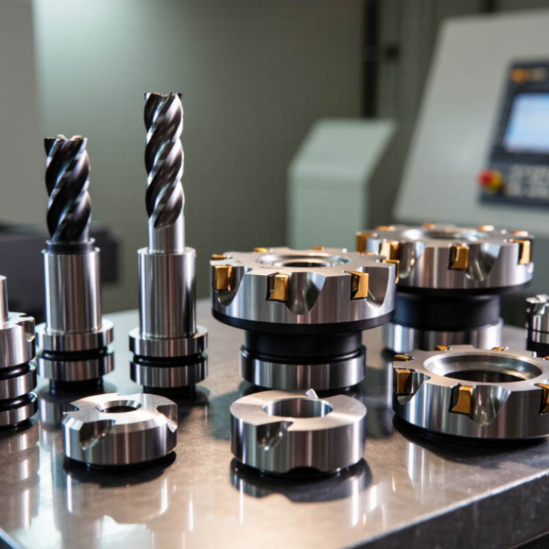
What Milling Tools Are and How They Remove Material
Milling tools are rotating cutters used to shape solid materials by removing small chips. A spindle turns the cutter while the workpiece or cutting head moves along a planned path. Each cutting edge meets the surface, shears away a thin layer, and leaves a new profile. This repeated action can create flat faces, slots, pockets, and curved contours. The process is controlled, but not effortless.
Cutter shape affects how material comes off. End mills can cut along their sides and ends, while face mills remove material across broader surfaces. Flutes provide space for chips to escape; poor chip clearance can cause rubbing, heat, or a rough finish. Tool material, edge geometry, cutting speed, and feed rate all matter. A cutter that works well in aluminum may perform poorly in hardened steel. Even a small setup error can leave chatter marks. It is tempting to blame the tool alone, but workholding and machine rigidity deserve a check, too.
Tips: Match the cutter to the operation and material. Secure the workpiece firmly, then clear chips before they crowd the cutting area. Listen for changes in sound and inspect the finish. A steady cut is useful evidence, though it does not guarantee the settings are ideal.
Common Types of Milling Tools and Their Cutting Functions
Milling tools remove material with rotating teeth, but each cutter leaves a different surface and chip pattern. USCTI and AMT’s 2023 cutting-tool consumption data put U.S. shipments at roughly $2.1 billion, showing the scale of this tooling sector. The figure measures shipments, not tool performance, so it cannot tell a machinist which cutter suits a specific job.
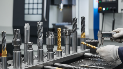
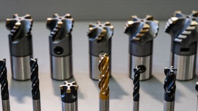
End mills are versatile. Flat-ended versions cut slots, pockets, and square shoulders; ball-nose end mills create curved contours and rounded transitions. Face mills use several replaceable cutting edges to level broad surfaces, while peripheral cutters machine along their sides to produce deep grooves or straight profiles. Small detail matters: a worn edge can leave visible ridges on a finish pass.
Drills make holes, but milling cutters can enlarge or shape them through circular interpolation. Chamfer mills add beveled edges, helping remove sharp corners before assembly. ISO 8688-2 sets out a tool-life testing method for end milling, emphasizing controlled comparisons rather than universal life claims. Still, choosing a cutter is rarely tidy. Material, chip evacuation, tool reach, and machine rigidity all change the result. A long-reach end mill may reach a deep pocket, yet chatter can spoil its walls.
Common Milling Tools and Their Cutting Functions
Representative cutting-edge counts for common cutter configurations. More cutting edges do not automatically mean faster machining; the suitable tool depends on the material, operation, and cutting conditions.
A 2-flute end mill is often used for slotting, while a 4-flute end mill is commonly used for profiling. Ball-nose end mills create contoured 3D surfaces, and face mills produce flat surfaces. The counts shown are example configurations; actual designs vary.
Materials and Shapes Milling Tools Can Machine
Milling tools machine steel, cast iron, aluminum, copper alloys, titanium, and some engineering plastics. The workpiece’s shape matters too. End mills cut slots, pockets, and profiles; face mills produce broad, flat surfaces; ball-nose cutters follow curved contours and 3D forms. Small details matter. A narrow slot needs a cutter that can reach its depth without rubbing the walls. Thin sections can also vibrate, even when the material seems easy to cut.
Steel remains a major machining material: the World Steel Association’s World Steel in Figures 2024 reports 1,888.2 million tonnes of global crude steel production in 2023. The International Aluminium Institute reported about 70.6 million tonnes of global primary aluminium production that year. These figures show the scale of two important material families, not how easily any specific grade mills. Aluminum often allows higher cutting speeds, but soft chips may stick to the cutting edge. Titanium can generate heat quickly, so tool geometry and coolant choices matter. Not every tool fits. A practical check is to match cutter shape and cutting conditions to the alloy, feature, and machine rigidity. That’s a useful guide, not a guarantee; I still need to check the actual setup.
Industries and Parts That Use Milling Tools
Milling tools are used across industries that need precise, repeatable shapes in metal, plastic, or wood. In automotive plants, cutters machine engine blocks, brackets, and gearbox housings. A flat end mill can form a pocket for a bearing, while a face mill smooths a broad surface. Small differences matter: a rough edge may prevent two parts from fitting properly.
Aerospace workshops use milling tools to shape lightweight components, including ribs, panels, and mounting features. Medical device makers machine instrument handles and durable component housings, often working to close tolerances. Tool and die shops cut molds, fixtures, and custom parts for production lines. Even furniture makers use milling cutters for grooves and joinery. The right tool depends on material, geometry, and finish requirements; there is no universal choice. In practice, setup and tool wear can complicate a job, even when the drawing looks clear.
Tips: Match the cutter to the material and feature. Secure the workpiece firmly, and check tool condition before cutting. A test pass helps reveal vibration or a poor finish. Don’t assume the first result is perfect.
How Tool Choice Affects Milling Results
What Are Milling Tools Used For?
How Tool Choice Affects Milling Results
Milling tools remove material with rotating cutting edges, but their shape and construction influence the finished part. A sharp end mill can cut a narrow slot cleanly, while a face mill covers a wider surface. The choice affects surface texture, accuracy, cutting force, and how quickly heat builds near the edge. Small details matter.
Material is a key factor. Aluminum often allows faster cutting, while harder steels may need tougher tools and more cautious settings. A tool with too many flutes can crowd chips in a deep cut. That can leave a rough finish or damage the edge. On a shop floor, checking the chips and listening for chatter can reveal trouble before a part is ruined.
Tool reach and rigidity matter, too. A long, slender cutter may reach a recessed feature, but it can deflect under pressure and leave a tapered wall. A shorter tool is usually steadier, though it may not reach every surface. There is no perfect choice for every setup. I’d treat recommended speeds as a starting point, then inspect the cut, measure the part, and adjust carefully. One missed detail can change the result.
 Skip to content




 English
 Russian
  German
  Spanish
  French
  Portuguese